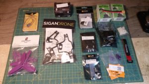
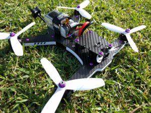
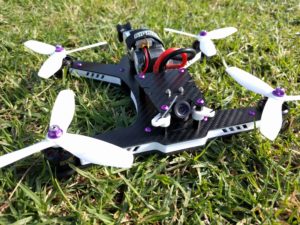
1. Components
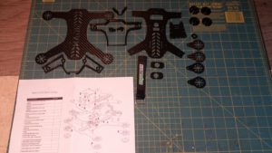
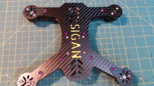
- Sigandrone Sigan250 v2 Frame Kit – White $190
- EMAX Skyline F3 Flight Controller (Acro) – $34
- 4x DYS SE2205 2300kv FPV Racing Motors – All CWW $100
- 4x DYS XMS30a Esc 30A Blheli oneshot solder version – $84
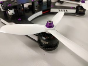
- M5 Motor Lock Nuts In Colours! (Set of 5) – Purple – $4
- Foxeer HS1177 XAT600M DC5V-22V 600tvl Sony Super HAD CCD FPV Camera IR Block 2.8mm Lens PAL – $53
- FrSky XSR 2.4GHz 16CH ACCST Receiver with S-Bus and CPPM $45
- TBS TRIUMPH Antennas (2 Pieces) -RP-SMA – $29 (for one)
- TBS UNIFY PRO 5G8 VTX Video Transmitter – $79
- Buzzer for Skyline32 Flight Control – $5
- Dal Prop MR1213 Tri Blade V2 T5045BN 5045BN Bullnose Propellers CW/CCW 1 Pack (4 Pieces) – $2.70
- Matek MICRO BEC 5V / 12V ADJ mbec2A – $4
- 6 Hours of your time – Priceless
Total Cost – $629.70 + $6 hours labour + Consumables.
2. Tips On Building
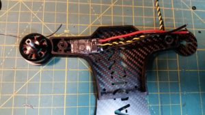
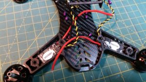
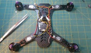
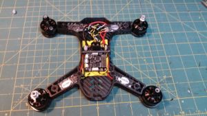
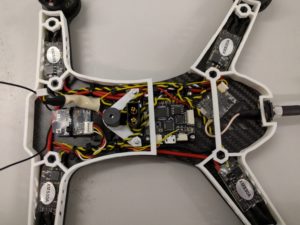
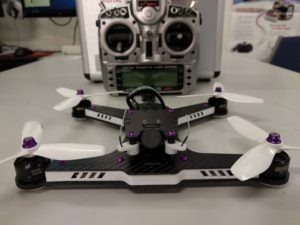
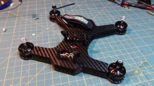
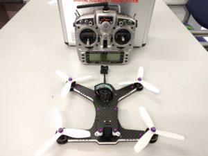
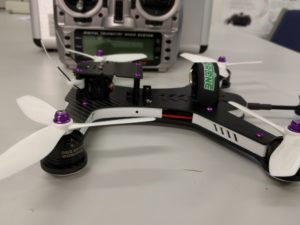
The Sigan drone is an award-winning compact racer with a very specific design requiring a tight and compact assembly of the electronics. It should not be attempted for those who are new or inexperienced in the craft. The build pics below are from the 210 and 250 class available from Phaser computers.
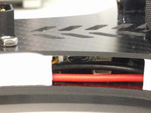
If you decide to use different components than those listed above please check to see if they will fit. The space between the top and bottom plates is around 10mm. Since all components bar the camera, buzzer and xt60 are intended to fit in this space anything higher than 10mm is essentially a problem.
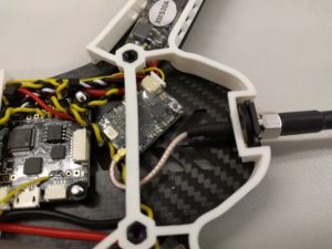
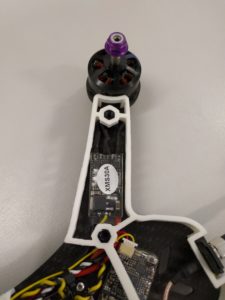
Once you have checked all your parts are there I recommend inserting your standoffs first and test fitting your escs. 20 amp esc’s are recommended for the 210 build, though the right 30 ampers can fit if you are careful. The 210 seen below has 30 amp DYS escs with solder tabs. Take special care when soldering the middle motor lead in particular, it will need to be slightly longer to accommodate wrapping around the body post. Test fit your 3D printed side skirt/bumper too, if your esc doesn’t fit inside you may as well stop now until you solve that. Everything should lay as flat as possible, motor leads will need to be short and soldered directly to the esc, especially in the case of the 210.
Mount your flight controller next. -90 or +90 so you can access the usb port. You may choose to use some longer bolts for the pdb and FC. There are holes on the top deck that line up with the pdbs bolts and I chose to lengthen these bolts to stiffen the pdb and center of the drone. When you solder in your xt60 connector remember to trim the bottom tabs off flush so they dont rub against the carbon fiber and cause a direct short. This will most likely end very badly if you aren’t careful.
Route all your power cabling down either side of the craft to the PDB, leaving enough room for the 3d printed skirts to fit and allowing access to the FC usb hub. Solder all connections directly to the FC where possible. Use the 5v regulator to power your FC and any other components like the VTX in this case.


